
Article Quick Summary
Learning how to build a parking structure starts with defining the parking need, expected users, vehicle types, site constraints, and governing requirements. Those decisions shape the layout, construction method, structural grid, foundations, ramps, drainage, and project budget.
A parking structure should be planned as infrastructure. It must withstand vehicle loads, water, road salt, freeze-thaw cycles, temperature changes, snow-removal equipment, and continuous public use.
The most successful projects coordinate parking planning, architecture, engineering, construction, manufacturing, drainage, and operations from the beginning. This guide explains that process step by step.
A parking structure is not simply a building that stores vehicles. It is transportation infrastructure exposed to demanding operating and environmental conditions.
Treat the Parking Structure as Infrastructure
A parking structure may look simpler than a hospital, office, or residential building. Its operating environment is often more demanding.
Vehicles carry water, snow, ice, road salt, and chlorides into the facility. Wind-driven precipitation enters through open façades. The roof level may be directly exposed to sun, rain, snow, temperature changes, and snow-removal equipment.
The structure must resist:
- Vehicle and pedestrian loads
- Snow and snow-drift loads
- Wind and seismic forces
- Vehicle impacts against barriers and columns
- Temperature changes and structural movement
- Repeated wetting, drying, and freeze-thaw cycles
- Snowplows and other maintenance equipment
- Continuous public use
A parking structure must function as several systems at once:
- A vehicle-storage system
- A vehicle-circulation system
- A pedestrian environment
- A structural system
- A drainage system
- A transportation asset
- A long-term operating and maintenance responsibility
Durability, drainage, inspection, and maintenance cannot be added near the end of design. They must influence the construction method, structural behaviour, materials, joints, slopes, and details from the beginning.
Owners looking for an early planning checklist can also review 30 Things to Know Before Building a Parking Structure.
Step 1: Define What the Parking Structure Must Accomplish
Before drawing the building, prepare a clear project brief. It should explain the parking problem, the required capacity, the expected users, and the owner’s long-term priorities.
Establish the parking requirement
Determine:
- The total number of parking spaces required
- Opening-day parking demand
- Long-term parking demand
- Public, employee, resident, fleet, and reserved spaces
- Accessible and van-accessible spaces
- Electric vehicle charging and EV-ready spaces
- Bicycle and motorcycle parking
- Pickup, delivery, and passenger-loading areas
A target stall count should not automatically become a fixed building size. The footprint and number of levels should result from an efficient layout that satisfies the parking requirement.
Understand the users
A hospital, airport, university, residential building, commuter station, and stadium may each need 1,000 spaces. They will not operate the same way.
Ask:
- Who will use the structure?
- When will peak arrivals and departures occur?
- Will drivers be familiar with the facility?
- Will large pickup trucks and sport utility vehicles be common?
- Will vehicles queue at gates, pay stations, or security checkpoints?
- Will the structure operate continuously?
- Will people use the facility alone at night?
- Where will pedestrians go after leaving their vehicles?
- Does the facility generate parking revenue?
These answers affect stall dimensions, circulation, entrances, elevators, lighting, signage, security, and pedestrian routes.
For examples of how user requirements differ, explore our guides to airport parking garage construction and stadium parking structure design and construction.
Confirm whether all projected parking is needed immediately
Before constructing a large capital asset, review:
- Existing parking utilization
- Peak-period demand
- Shared-parking opportunities
- Transit availability
- Transportation demand management
- Planned development on the surrounding site
- Opportunities for future expansion
A structure designed for future horizontal or vertical expansion may provide better value than building all projected capacity at once.
Establish owner priorities
Owners should identify their priorities before design begins. Common priorities include:
- Lowest initial construction cost
- Fastest completion
- Reduced disruption to an active site
- Long service life
- Low maintenance requirements
- Architectural appearance
- Future expansion
- Reduced structural weight
- Open and comfortable parking areas
- Minimal operational shutdowns
Some objectives reinforce each other. Others require tradeoffs. The project team should document those tradeoffs instead of allowing them to emerge after design is advanced.
Create a Basis of Design
The Basis of Design should document:
- Owner and user requirements
- Parking-space requirements
- Vehicle assumptions
- Applicable codes, standards, and bylaws
- Site and traffic assumptions
- Design loads
- Clear-height requirements
- Durability and service-life objectives
- Construction-method assumptions
- Drainage strategy
- Accessibility requirements
- Security and Crime Prevention Through Environmental Design objectives
- Electrical and electric vehicle requirements
- Future-expansion requirements
- Budget and schedule targets
The Basis of Design should be updated as the owner and project team confirm major decisions.
Step 2: Investigate the Site, Codes, Traffic, and Soil
The structure cannot be designed in isolation from the property beneath and around it. Site restrictions can affect the footprint, number of levels, foundation system, crane locations, entrances, and construction sequence.
Complete site due diligence
Review:
- Property boundaries
- Easements and setbacks
- Height restrictions
- Lot coverage
- Existing buildings and utilities
- Underground services
- Fire-department access
- Stormwater and sewer capacity
- Existing and proposed entrances
- Adjacent roads and intersections
- Construction staging space
- Delivery and crane access
- Overhead power lines
- Environmental conditions
- Floodplain restrictions
- Airport or transportation-corridor restrictions
Study traffic outside the structure
Vehicle circulation does not begin at the entrance gate. An efficient internal layout can still perform poorly if vehicles queue onto the surrounding road.
Evaluate:
- Entry and exit queueing
- Gate, payment, and security delays
- Left-turn and right-turn movements
- Nearby traffic signals
- Peak arrival and departure patterns
- Event-related traffic
- Conflicts with pedestrians and cyclists
- Emergency and service access
- Snowbanks near entrances and sightlines
Identify the applicable codes and standards
The legally adopted code may not be the latest published model code. Create a code and standards register that identifies:
- The governing document
- The adopted edition
- Provincial, state, or local amendments
- The responsible design discipline
- The reviewing authority
- The applicable project requirement
- Outstanding interpretations or approvals
Common Canadian requirements
Canadian projects may need to consider:
- The adopted provincial or territorial building code
- The adopted fire code
- Municipal zoning and parking bylaws
- The National Building Code of Canada, where adopted or referenced
- CSA S413, Parking Structures
- CSA A23.1 and CSA A23.2 for concrete materials, construction, and testing
- CSA A23.3 for concrete structural design
- CSA A23.4 for precast concrete materials and construction
- CSA S16 where structural steel is used
- Applicable accessibility requirements
- The Canadian Electrical Code
- Plumbing and drainage codes
- Municipal stormwater and sewer requirements
- Owner-specific or agency-specific criteria
CSA S413 addresses durability requirements for new parking structures and areas exposed to vehicle traffic. See CSA S413 for Parking Structures for a practical overview.
Common United States requirements
United States projects may need to consider:
- The adopted state or local building code, often based on the International Building Code
- The adopted fire code
- Local zoning and parking ordinances
- ASCE/SEI 7 for structural loads
- ACI 318 for structural concrete
- ACI 301 where specified for concrete construction
- National Fire Protection Association Standard 88A where adopted
- National Fire Protection Association Standard 70, the National Electrical Code
- Applicable Precast/Prestressed Concrete Institute standards
- The Americans with Disabilities Act Standards for accessible parking
- ICC A117.1 where adopted
- Mechanical, plumbing, and energy codes
- Federal, airport, hospital, transit, or institutional requirements
Codes establish minimum requirements. Owners may choose enhanced criteria for service life, vehicle size, lighting, security, future expansion, durability, or maintenance.
Complete a project-specific geotechnical investigation
The geotechnical investigation should establish:
- Allowable soil-bearing capacity
- Total and differential settlement
- Depth to competent bearing material
- Groundwater elevation
- Frost depth
- Existing or undocumented fill
- Compressible or organic soils
- Rock elevation
- Liquefaction potential where applicable
- Seismic site classification
- Excavation and dewatering requirements
- Potential contamination
Regional geotechnical information can support early feasibility. It should not replace site-specific boreholes and engineering recommendations.
Step 3: Select the Project-Delivery and Construction Methods
For owners deciding how to structure the competition itself, see Parking Structure Procurement: Define the Outcome Before the Solution, which looks at performance requirements, qualifications, professional-services competition and when detailed design should occur.
Parking geometry, structural design, drainage, foundations, manufacturing, and construction logistics affect one another. The project-delivery method should allow these decisions to be coordinated before they are fixed.
Why isolated handoffs create problems
A conventional sequence may involve a parking layout being handed to an architect, the architectural drawings being handed to a structural engineer, and the completed documents being handed to a contractor for pricing.
That sequence can overlook several relationships:
- The parking module affects the structural grid.
- The structural grid affects the construction method.
- The construction method affects structural depth and clear height.
- Building weight affects foundations and seismic forces.
- Ramp geometry affects building length and floor-to-floor height.
- Drainage affects floor slopes, joints, and structural detailing.
- Component dimensions affect transportation and crane access.
- Construction phasing affects temporary parking and site access.
- The façade affects open-air classification and ventilation.
Use an integrated design-build process
An integrated parking structure design-build team can coordinate parking planning, architecture, engineering, estimating, manufacturing, logistics, and construction before the design is locked in.
Progressive Design-Build can also allow the owner to select an integrated team early, develop the design collaboratively, and establish the final price after major risks are better understood.
Function establishes the essential geometry. Architecture gives that geometry an appropriate form and civic presence.
This approach does not reduce the role of architecture. It prevents an exterior concept from forcing inefficient parking, structural, and circulation decisions into the space that remains.
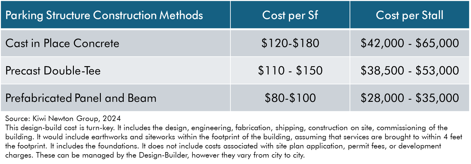
Compare the three main parking structure construction methods
Owners planning an above-grade structure will commonly compare:
- Cast-in-place concrete
- Ultra-high-performance concrete panel-and-beam
- Precast double-tee
Ultra-high-performance concrete is commonly abbreviated as UHPC. UHPC panel-and-beam should be considered in the same construction-method discussion as cast-in-place concrete and precast double-tee.
| Construction method | How it works | Common applications | Key considerations |
|---|---|---|---|
| Cast-in-place concrete | Concrete is formed, reinforced, placed, and cured on site. | Complex geometry, below-grade work, and highly customized structures. | Formwork, shoring, curing, weather, field labour, crack control, and driving-surface protection. |
| UHPC panel-and-beam | Prefabricated UHPC deck panels are installed on structural beams and connected as a coordinated assembly. | Above-grade structures, open-span layouts, accelerated erection, and projects prioritizing durable driving surfaces. | Early engineering, repetitive grids, manufacturing tolerances, transportation, crane access, connections, and interface responsibility. |
| Precast double-tee | Large prestressed double-tee members span between beams, walls, or other supports. | Conventional precast parking structures using established production and erection practices. | Structural depth, flange joints, connections, topping or membrane strategy, transportation, and layout constraints. |
Cast-in-place concrete
Cast-in-place structures are formed and poured at the project site. Reinforcing steel, formwork, shoring, concrete placement, curing, and reshoring are major parts of the sequence.
Potential advantages include:
- Flexible geometry
- Ability to accommodate irregular footprints
- Familiar structural design practices
- Monolithic construction
- Suitability for below-grade work
Potential considerations include:
- Substantial site labour
- Formwork and shoring
- Weather-dependent activities
- Curing and reshoring cycles
- Site-dependent finish and quality control
- Driving-surface protection and crack control
UHPC panel-and-beam
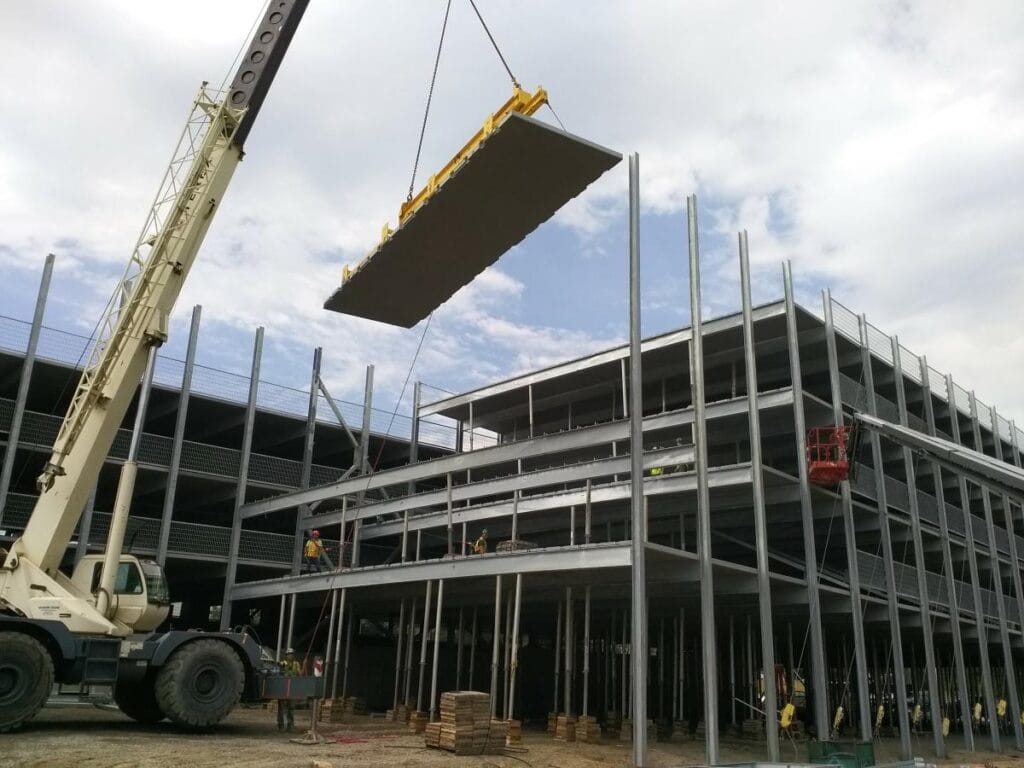
UHPC panel-and-beam construction uses prefabricated deck panels supported by structural beams. The panels, beams, joints, and connections are engineered as a coordinated assembly.
Potential advantages include:
- Controlled off-site production
- Rapid on-site erection
- Thin, low-permeability deck components
- Reduced structural mass
- Less field forming and curing
- Potentially lower foundation demand
- Open spans and visible primary beams
- Coordinated structural, drainage, and joint design
Potential considerations include:
- Early structural and architectural coordination
- A rational and repetitive grid
- Transportation limits
- Delivery and crane access
- Manufacturing and erection tolerances
- Clear responsibility among designers, manufacturers, and erectors
- Project-specific detailing for unusual geometry
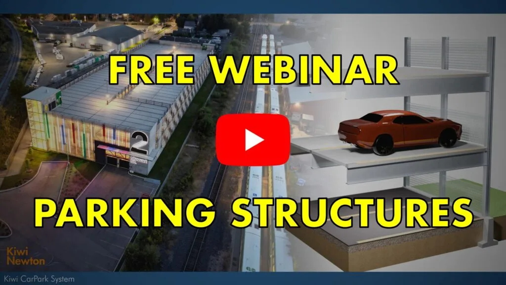
The Kiwi CarPark System is Kiwi Newton’s implementation of UHPC panel-and-beam construction. It combines UHPC deck panels, galvanized structural steel, and integrated design-build delivery.
Precast double-tee
Precast double-tee structures use large prestressed members produced off site. The members are transported to the project, erected, and connected to form the deck.
Potential advantages include:
- Established North American production capacity
- Rapid structural erection
- Long-span capability
- Reduced site forming
- Factory production of major members
Potential considerations include:
- Structural depth
- Transportation and crane requirements
- Numerous flange joints
- Connection maintenance
- Topping or membrane requirements
- Layout constraints on irregular sites
For a deeper comparison, see The UHPC Panel-and-Beam Construction Method for Parking Structures.
Use the same evaluation criteria for each method
Compare each construction method using the same questions:
- How deep is the floor system?
- How much does the completed structure weigh?
- How does the system affect the foundations?
- What grid and layout restrictions apply?
- How much forming, curing, and site labour are required?
- Can structural components be produced while foundations are built?
- How many joints are present?
- Where does tension occur in the exposed driving surface?
- How are cracking and chloride exposure controlled?
- How is water drained from the deck?
- Which elements are visible and inspectable?
- Which membranes, toppings, coatings, or sealants will require replacement?
- How does the method affect the schedule?
- Can the structure be expanded later?
Step 4: Establish the Parking Dimensions and Layout
Parking dimensions are usually governed by zoning, accessibility requirements, owner criteria, and the vehicles expected to use the facility.
Confirm the required dimensions
Identify:
- Standard stall width
- Standard stall length
- Accessible stall dimensions
- Van-accessible stall dimensions
- Access-aisle dimensions
- Drive-aisle width
- Turning radii
- Ramp width
- Maximum ramp slope
- Maximum parking-floor slope
- Vertical clearance
- Bicycle and motorcycle requirements
Use project-specific dimensions
Illustrative dimensions might include:
- Stall width: 2.6 to 2.8 m, or approximately 8 ft 6 in to 9 ft 2 in
- Stall length: 5.6 to 6.0 m, or approximately 18 ft 4 in to 19 ft 8 in
- Two-way aisle: 6.0 to 6.5 m, or approximately 19 ft 8 in to 21 ft 4 in
- Clear height: approximately 2.1 m, or approximately 6 ft 11 in, subject to vehicle routes and governing requirements
These are examples, not universal standards. Confirm the zoning bylaw, accessibility requirements, building code, and owner criteria for every project.

Define the parking bay
A typical double-loaded parking bay consists of:
Parking stall length + drive aisle + parking stall length
For example:
- Stall length: 5.9 m
- Drive aisle: 6.2 m
- Stall length: 5.9 m
- Total bay width: 18 m, or approximately 60 ft
Depending on the governing dimensions, a double-loaded bay may be approximately 17.2 to 18.5 m wide, or approximately 56 to 61 ft.
The bay width affects:
- Building width
- Structural spans
- Column positions
- Ramp configuration
- Drainage direction
- Lighting
- Façade repetition
- Construction efficiency
Measure parking efficiency
A useful early planning measure is:
Gross floor area ÷ total number of parking spaces
Gross floor area should include stalls, drive aisles, ramps, stairs, elevators, pedestrian circulation, and required service rooms.
For an efficient above-grade layout, approximately 28 m², or 300 sq. ft., per stall can be a useful early planning benchmark. Results above approximately 32.5 m², or 350 sq. ft., may indicate that ramps, irregular geometry, circulation, or non-parking spaces are reducing efficiency.
These are planning benchmarks, not mandatory limits. A hospital structure with generous pedestrian routes or a compact one-bay structure with a dedicated ramp may require more area per stall.
The least expensive square footage is the square footage the project does not need to build.
Efficiency should not be achieved by compromising:
- Comfortable stall dimensions
- Turning movements
- Accessible routes
- Pedestrian safety
- Queueing
- Sightlines
- Snow removal
- Required service spaces
Recalculate area per stall during feasibility, concept design, schematic design, design development, and preconstruction. When the number increases, identify the reason before the design progresses.
Step 5: Select the Ramps, Circulation, and Clear Heights
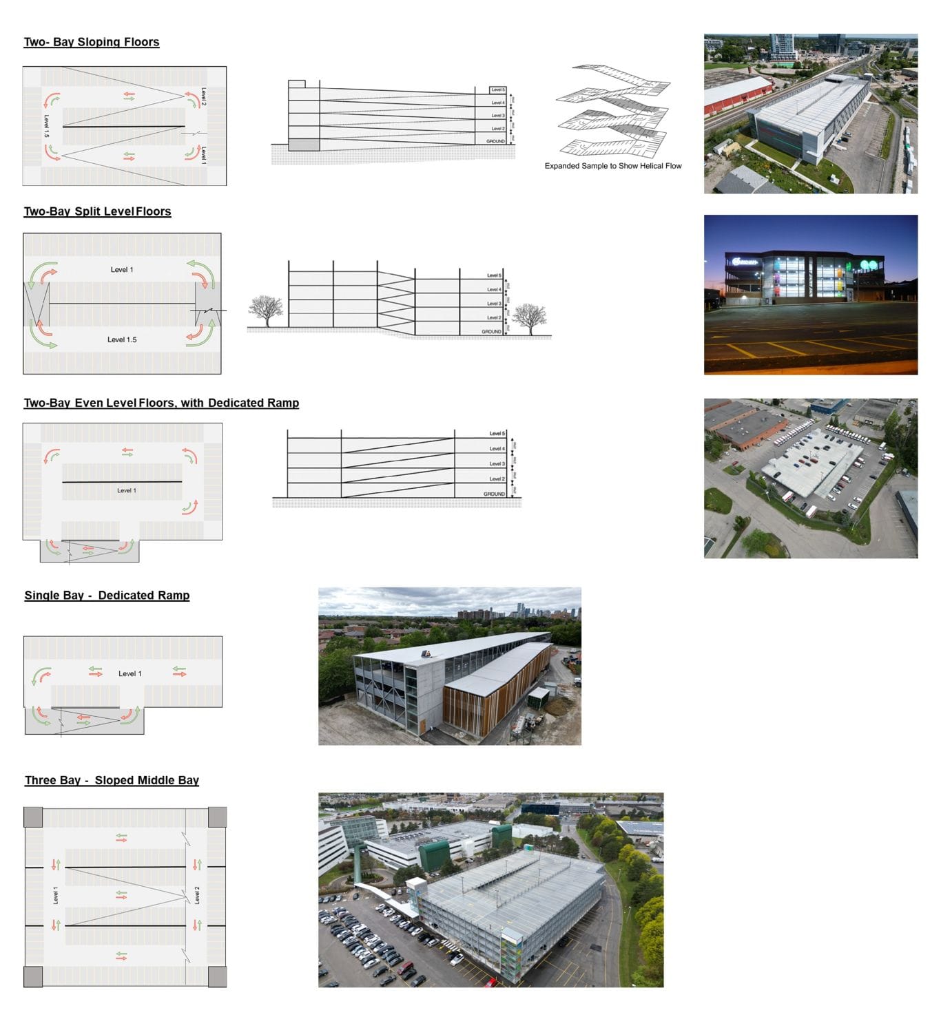
Parking structures commonly use three circulation arrangements:
- Dedicated ramps
- Sloping floors
- Split-level systems
Dedicated ramps
A dedicated ramp is separate from the main parking floor. It may carry one-way or two-way traffic.
Consider:
- Ramp width
- Maximum slope
- Transition slopes
- Landings
- Queueing
- Turning movements
- Sight distance
- Snow and ice
- Ramp area
- Parking spaces displaced by the ramp
A one-bay parking structure will generally require a dedicated ramp or another separate vertical-circulation solution. The Carillon Parking Structure is an example of a one-bay layout with a dedicated ramp.
Sloping floors
In a sloping-floor structure, part of the parking floor gradually rises to the next level. Parking may remain on the sloped surface where the permitted slope and accessibility requirements allow.
A simplified early calculation is:
Required sloping length = floor-to-floor height ÷ permitted slope
A 2.7 m floor-to-floor height at a 5% slope requires approximately 54 m, or 177 ft, of sloping length. Turning zones, transitions, and structural-grid increments may increase the required building length.
Sloping-floor arrangements are generally more practical in structures with two or more parking bays. The Joseph Street Parking Structure demonstrates a two-bay sloping-floor layout.
Split-level systems
A split-level arrangement uses shorter elevation changes between adjacent parking bays. Each bay may be approximately half a level above or below the next.
Potential advantages include:
- Shorter ramp segments
- Reduced dedicated-ramp area
- Efficient use of drive aisles
- Compact vertical circulation
Potential considerations include:
- Driver wayfinding
- Repeated half-level changes
- Elevator and accessible-route coordination
- Structural and drainage complexity
The Centennial GO Station parking structure is an example of a split-level arrangement.
Establish clear height
Clear height is the unobstructed vertical space available to vehicles. The lowest installed item controls the actual clearance.
Check:
- The underside of decks and beams
- Lighting
- Pipes
- Signs
- Sprinklers where required
- Security and parking equipment
- Structural deflection
The design should distinguish between:
- Required vehicle clearance
- Actual clear height
- Posted clearance
- Accessible-van route clearance
Consider the expected vehicles
Review the needs of:
- Passenger cars
- Pickup trucks
- Sport utility vehicles
- Accessible vans
- Fleet and service vehicles
- Ambulances where applicable
- Vehicles with roof-mounted equipment
- Snow-removal equipment
Establish floor-to-floor height
Floor-to-floor height includes:
- Required clear height
- Structural depth
- Drainage slopes
- Lighting and services
- Construction tolerances
- Deflection allowances
Reducing unnecessary floor-to-floor height can reduce:
- Overall building height
- Façade area
- Ramp length
- Column length
- Stair and elevator travel
- Structural material quantities
- Visual mass
The selected height must still accommodate every required vehicle route and installed system.
Step 6: Coordinate the Structure, Weight, and Foundations
Align the structural grid with the parking module
The structural grid should:
- Follow the parking-bay geometry
- Keep columns out of drive aisles where practical
- Minimize interference with stalls
- Coordinate with ramps and level changes
- Support efficient spans
- Coordinate with stairs and elevators
- Support the drainage strategy
- Allow repetitive manufacturing and construction
- Accommodate façades and vehicle barriers
- Support future expansion where required
The grid must also coordinate with foundations, expansion joints, component transportation, erection sequencing, and crane access.
Design for applicable loads
Structural design may need to address:
- Dead load
- Vehicle and pedestrian live loads
- Snow and snow drifting
- Rain and ponding
- Wind
- Seismic effects
- Thermal movement
- Shrinkage and creep
- Vehicle impact
- Barrier loads
- Construction and erection loads
- Snow-removal equipment
- Future expansion loads
Understand why building weight affects the project
A lighter structure may create:
- Lower column reactions
- Lower foundation loads
- Smaller foundations, depending on site conditions
- Less excavation
- Less foundation concrete and reinforcing
- Reduced demand on lower-bearing-capacity soils
Lower structural weight does not automatically eliminate piles or deep foundations. Settlement, groundwater, column spacing, lateral loads, and soil conditions still control the final foundation design.
Consider building mass in seismic design
Seismic forces are inertial forces generated as the mass of a structure accelerates during an earthquake. When other factors are held equal, reducing effective seismic weight generally reduces the forces resisted by the lateral system and foundations.
Actual seismic performance also depends on:
- Regional seismic hazard
- Site classification
- Structural period
- Stiffness
- Ductility
- The lateral-force-resisting system
- Building importance
- Structural regularity
- Connection detailing
A lighter building is not automatically a better seismic building. The complete system must provide the required strength, stiffness, ductility, load paths, and connections.
Control tension and cracking in the driving surface
The top of a parking deck is directly exposed to water, road salt, freeze-thaw cycles, tire wear, and repeated vehicle loading.
Concrete is strong in compression and weaker in tension. Reinforcing steel can carry tensile forces after cracking, but cracks in an exposed surface may provide pathways for water and chlorides.
The structural and durability strategy should:
- Limit tensile demand at the exposed surface where practical
- Control crack widths
- Reduce unnecessary joints
- Protect reinforcement and connections
- Keep salt-laden water away from vulnerable materials
- Keep joints and cracks accessible for inspection
- Coordinate structural behaviour with drainage
Understand where top-surface tension occurs
Continuous structural behaviour can create negative moments over supports. This places the top of a concrete deck in tension near the support.
In cast-in-place systems, the reinforcement and crack-control strategy must account for this behaviour.
In double-tee systems, the designer and owner should understand:
- How the flange spans between stems
- How adjacent flanges are connected
- How wheel loads are distributed
- How temperature movement and restraint are accommodated
- How any topping or protection system behaves
- How cracks near stems, supports, or connections are controlled
Properly designed, detailed, constructed, and maintained double-tee structures can perform well. The exposed driving surface still needs to be evaluated as part of the structural and durability strategy.
Understand panel-and-beam behaviour
Depending on the selected panel, beam, connection, and composite design, a UHPC panel-and-beam system may reduce continuous negative-moment demand in portions of the exposed driving surface.
Movement and localized tension can be managed through engineered joints, reinforcement, and connections. The low permeability of UHPC can also slow the movement of water and chlorides through the concrete.
This does not remove the need for good engineering, drainage, joints, inspection, and maintenance.
Ask each structural-system provider where tension occurs in the exposed driving surface and how cracking, joints, and chloride exposure are controlled.
For related technical discussions, see Steel Beams in Parking Structures and Why Parking Structures Collapse.
Determine whether the structure can be open-air
Early in design, determine whether the facility will be:
- An above-grade open-air parking structure
- An enclosed parking structure
- An underground structure
- A partially below-grade structure
- Connected to another building
- Part of a mixed-use development
- Supporting another occupancy above
Open-air classification is determined by the governing code. It commonly depends on perimeter openings, the distribution of those openings, and the distance from interior areas to the exterior.
The classification may affect:
- Natural or mechanical ventilation
- Fire-resistance requirements
- Fire-protection systems
- Smoke control
- Façade openings
- Allowable building area and height
- Construction type
- Operating energy
- Capital and maintenance costs
Requirements for sprinklers, standpipes, alarms, structural fire protection, and ventilation vary by jurisdiction and building configuration.
See Open-Air Parking Structures for a more detailed explanation.
Step 7: Design for Drainage, Durability, Accessibility, and Safety
Follow the water
- Vehicles carry rain, snow, ice, and road salt into the structure.
- Wind carries precipitation through open façades.
- Water moves across the deck.
- Floor slopes direct it toward drains, scuppers, or trench drains.
- Cracks, joints, penetrations, and connections are exposed along the route.
- The drainage system carries the water away.
- The system must continue to function during freezing conditions.
Drainage is not only a plumbing issue. It affects floor elevations, structural slopes, ramp geometry, joints, and long-term durability.
Coordinate drainage with the structure
Address:
- Primary and secondary floor slopes
- Point drains and trench drains
- Entrance drainage
- Scuppers and downpipes
- Drain-piping routes
- Expansion and construction joints
- Panel joints
- Service penetrations
- Freeze protection
- Salt-laden runoff
- Water dripping onto vehicles below
- Access for inspection and cleaning
Ask practical questions:
- Can each drain be reached and cleaned?
- What happens if a drain freezes or becomes blocked?
- Where will water pond if the primary drain fails?
- Are joints located over parked vehicles?
- Can water reach concealed reinforcement or connections?
- How will salt-laden runoff be collected and discharged?
- Who is responsible for the interface between the structure and drainage system?
Choose a complete durability strategy
The strategy may include:
- Low-permeability concrete
- Adequate concrete cover
- Crack control
- Traffic-bearing membranes or toppings where required
- Durable joint systems
- Protected reinforcement
- Hot-dip galvanized structural steel
- Stainless or protected components in severe exposure zones
- Visible and inspectable details
- A defined washing and maintenance program
For more information about visible corrosion protection, see Galvanized Steel for Parking Structure Construction.
Plan for snow and winter operations
In Canada and northern regions of the United States, address:
- Top-deck snow removal
- Designated snow-storage areas
- Snow-drop zones
- Concentrated snow-pile loads
- Plow routes and turning movements
- Plow impact on barriers and façades
- Ramp icing
- Frozen drains
- De-icing materials
- Snowmelt runoff
- Freeze protection for exposed pipes
- Snow-removal equipment weight
Operators should know where snow may be stored and where it must not be stockpiled. Concentrated snow loads can exceed the assumptions used for normal roof loading.
Plan pedestrian routes early
Identify:
- Where people enter and leave the structure
- Destination buildings and site paths
- Accessible routes
- Protected pedestrian walkways
- Drive-aisle crossings
- Stair and elevator locations
- Travel distances
- Weather protection
- Passenger-loading areas
- Conflicts at vehicle entrances and exits
Stairs and elevators should be located where people naturally want to go. They should not be placed in leftover spaces after the parking layout is complete.
Coordinate accessibility
Confirm:
- The number and distribution of accessible spaces
- Van-accessible stalls
- Access aisles
- Accessible vertical clearances
- Accessible routes to entrances and elevators
- Surface slopes
- Door and gate operation
- Pay stations and access-control equipment
- Passenger-loading zones
- Signage
Accessibility requirements vary between Canadian jurisdictions and between federal, state, and local requirements in the United States. Confirm the governing criteria before fixing the layout and clear heights.
Use Crime Prevention Through Environmental Design
Crime Prevention Through Environmental Design, commonly called CPTED, should influence the parking layout and architecture from the beginning.
Consider:
- Long sightlines
- Natural surveillance
- Open drive aisles
- Minimal visual obstructions
- Visible elevators
- Open or glazed stair towers
- Uniform lighting
- Reduced glare
- Minimal hiding places
- Clearly defined entrances and exits
- Wayfinding
- Camera coverage
- Emergency communication
- Access control where appropriate
- A clean and well-maintained appearance
Open structural spans can improve visibility between pedestrians and drivers. Projects such as Centennial GO Station demonstrate how structure and architecture can support sightlines and user comfort.
See CPTED for Parking Structures for a deeper discussion.
Design vehicle barriers as structural systems
Vehicle barriers, guards, and façade protection are structural safety systems.
Coordinate:
- Code-specified vehicle impact loads
- Barrier height and geometry
- Connections to the primary structure
- Protection around openings and ramps
- Column protection
- Snowplow impact
- Pedestrian fall protection
- Façade attachments
Step 8: Plan Electrical Systems, Technology, and Future Expansion
Electrical and parking technology should be planned before the structural design is complete. Late additions can require visible conduit, new penetrations, larger service rooms, and costly electrical upgrades.
Plan electric vehicle charging
Establish:
- The opening-day charger count
- The future charger count
- The number of EV-ready spaces
- Electrical-service capacity
- Transformer requirements
- Load management
- Panel and electrical-room locations
- Conduit pathways
- Future rough-ins
- Protection from vehicles, water, and salt
- Maintenance and replacement access
The decision is not only how many chargers to install today. The service, distribution system, and pathways should support planned future expansion.
Coordinate parking and security technology
Consider:
- Lighting and lighting controls
- Emergency power
- Access and revenue control
- Barrier gates
- Security cameras
- Emergency call stations
- Parking-count systems
- Space-availability signs
- Licence-plate recognition
- Cellular and Wi-Fi coverage
- Digital wayfinding
- Building-management integration
Consider solar energy and mobility uses
A parking structure can also support:
- Electric vehicle charging
- Solar photovoltaic systems
- Battery storage
- Bicycle and micromobility facilities
- Transit or shuttle connections
The Humber College parking structure demonstrates how parking, solar power, electric vehicle charging, bicycle storage, and occupied spaces can be combined within a campus project.
Develop the architectural form around the function
After the functional geometry is established, architecture should address:
- Relationship to surrounding buildings
- Street frontage
- Pedestrian scale
- Façade openness
- Screening
- Glare and light spill
- Noise
- Signage and branding
- Public art
- Ground-floor activity
- Material durability
- Façade maintenance
- Snowplow and vehicle impact
An attractive and context-sensitive exterior does not need to compromise parking function, sightlines, ventilation, or long-term durability.
Design future expansion into the initial project
Expansion may be:
- Vertical, by adding more levels
- Horizontal, by adding another parking bay
- Operational, by adding chargers or parking technology
- Programmatic, by adding solar, bicycle facilities, or occupied space
Future expansion affects foundations, columns, lateral systems, stairs, elevators, ramps, drainage, permits, and construction access. It must be designed into the original project rather than assumed later.
Step 9: Plan Construction, Quality Control, and Site Operations
A technically efficient parking structure may still be difficult or expensive to build if logistics are not considered during design.
Plan cast-in-place construction logistics
Address:
- Formwork
- Shoring and reshoring
- Reinforcing delivery and storage
- Concrete-truck routes
- Pump locations
- Pour sequencing
- Curing
- Winter protection
- Site labour
- Temporary access
- Form removal and material handling
Plan prefabricated construction logistics
Address:
- Component dimensions and weights
- Transportation routes
- Road and bridge restrictions
- Truck turning and unloading
- Delivery sequencing
- On-site storage
- Crane size and reach
- Crane setup locations
- Overhead restrictions
- Temporary bracing
- Erection tolerances
- Weather limits
- Just-in-time delivery
- Stability of the partially completed structure
Airports, hospitals, campuses, and urban sites may restrict delivery hours, crane heights, road closures, noise, and access. These restrictions should influence the structural and erection plans.
The Ronald Reagan Washington National Airport parking project illustrates the coordination required between foundations, delivery, crane planning, phasing, and active-site operations.
Use concurrent work where appropriate
An integrated prefabricated design-build process may allow several activities to overlap:
- Sitework and foundations
- Structural design
- Shop drawings
- Production planning
- Component manufacturing
- Long-lead procurement
- Construction logistics
The schedule advantage comes from coordinating design, engineering, production, delivery, and erection as one process.
See How Long Does It Take to Build a Parking Structure? for additional schedule information.
Maintain operations during construction
Plan for:
- Temporary parking
- Staff and public shuttles
- Emergency access
- Pedestrian detours
- Construction separation
- Partial openings
- Noise and dust
- Adjacent building access
- Utility continuity
- Traffic control
Quantify:
- Existing spaces temporarily lost
- The duration of the loss
- Temporary-parking costs
- Shuttle costs
- Lost revenue
- Operational disruption
Establish a quality plan
The quality program should address:
- Design reviews
- Material qualifications
- Concrete testing
- Plant quality control
- Shop-drawing review
- Weld inspection
- Galvanizing inspection
- Connection inspection
- Foundation surveys
- Anchor and embed verification
- Erection tolerances
- Joint mockups
- Drainage testing
- Façade interfaces
- Deficiency tracking
- As-built verification
Assign interface responsibility
Clearly assign responsibility for:
- Foundations to columns
- Columns to beams
- Beams to deck components
- Panels or tees to joints
- Structure to drainage
- Structure to vehicle barriers
- Structure to façade
- Structure to stairs and elevators
- Structural openings and building services
Integrated responsibility reduces gaps between separate designers, suppliers, and contractors.
Step 10: Commission and Maintain the Completed Structure
Compare lifecycle value
Do not compare construction methods using initial price alone. Evaluate:
- Initial construction cost
- Cost per parking space
- Cost per square metre or square foot
- Construction duration
- Temporary-parking and operational costs
- Membrane or topping replacement
- Joint maintenance
- Drain cleaning
- Concrete and corrosion repairs
- Painting or recoating
- Lighting and ventilation energy
- Inspection access
- Future rehabilitation
- Operational shutdowns
- Expansion capability
- Residual value
Consider inspectability
Ask:
- Can the primary structural elements be seen?
- Can joints be reached?
- Can corrosion be detected early?
- Can drains be cleaned easily?
- Can localized repairs be completed without major demolition?
- Are protection systems replaceable?
- Can the owner assess the structure without widespread destructive investigation?
Commission the structure before opening
Complete:
- Drainage testing
- Lighting verification
- Access-control testing
- Parking-technology testing
- Elevator commissioning
- Fire and life-safety inspections
- Vehicle-barrier inspections
- Accessibility review
- Wayfinding review
- Clearance verification
- Deficiency correction
- Final cleaning
Provide a complete turnover package
The owner should receive:
- As-built drawings
- Operations and maintenance manuals
- Warranties
- Inspection schedules
- Joint-maintenance requirements
- Drain-cleaning procedures
- Snow-removal limitations
- Allowable loading information
- A baseline condition survey
- Training for facilities staff
Maintain the facility as infrastructure
A long service life depends on both the original design and disciplined maintenance.
Establish a program for:
- Routine washing and chloride removal
- Drain inspections
- Joint inspections
- Concrete inspections
- Steel and coating inspections
- Barrier inspections
- Lighting maintenance
- Annual condition reviews
- Periodic structural assessments
- Repair prioritization
- Maintenance records
Frequently Asked Questions About How to Build a Parking Structure
What are the main steps for building a parking structure?
Define the parking need, investigate the site and soil, confirm the governing requirements, select the delivery and construction methods, design the layout and circulation, coordinate the structure and foundations, develop the drainage and durability strategy, plan construction, commission the facility, and establish a maintenance program.
What are the three main parking structure construction methods?
The three main methods are cast-in-place concrete, UHPC panel-and-beam, and precast double-tee construction. Each method should be compared using the same criteria for layout, structural depth, weight, foundations, schedule, durability, joints, maintenance, and lifecycle value.
How much area is needed per parking space?
An efficient above-grade layout may use approximately 28 m², or 300 sq. ft., of gross floor area per parking space. Ramps, irregular sites, stairs, elevators, accessible routes, and service areas can increase the result.
How wide is a typical parking bay?
A double-loaded parking bay may be approximately 17.2 to 18.5 m wide, or approximately 56 to 61 ft. The final dimension depends on the required stall lengths and drive-aisle width.
Can a one-bay parking structure use a sloping-floor layout?
A one-bay structure will generally require a dedicated ramp or another separate vertical-circulation solution. Sloping-floor and split-level arrangements are usually more practical when the structure has two or more parking bays.
How long must a sloping parking floor be?
The required length depends on the floor-to-floor height and the permitted slope. Gaining 2.7 m of elevation at a 5% slope requires approximately 54 m, or 177 ft, before accounting for transitions, turning areas, and structural-grid increments.
What determines floor-to-floor height?
Floor-to-floor height is determined by vehicle clearance, structural depth, drainage slopes, lighting, signs, pipes, other services, deflection, and construction tolerances.
Why does parking structure weight affect foundations?
Building weight affects column reactions and foundation loads. A lighter structure may reduce footing sizes, excavation, concrete, reinforcing, and demand on weak soils, although the final design still depends on settlement, groundwater, lateral loads, and site conditions.
Why is drainage critical in a parking structure?
Vehicles and weather bring water and road salt into the facility. Effective slopes, drains, joints, and piping reduce ponding and limit the time salt-laden water remains in contact with structural materials.
Can a parking structure be expanded later?
Some parking structures can be designed for future vertical or horizontal expansion. The original foundations, columns, lateral system, stairs, elevators, ramps, drainage, and approvals must account for the future construction.
How to Build a Parking Structure by Making Decisions in the Right Order
Understanding how to build a parking structure requires more than choosing a structural system and preparing construction drawings. Parking demand, site conditions, dimensions, circulation, construction method, structural grid, foundations, drainage, durability, safety, and operations must work together.
The strongest opportunities to improve cost, schedule, and long-term performance occur early. Once the footprint, parking layout, structural system, and procurement documents are fixed, changing direction becomes slower and more expensive.
An integrated design-build process allows the owner, parking planner, architect, engineers, manufacturer, and contractor to resolve these relationships while meaningful options remain available.
To review completed facilities, visit Kiwi Newton’s parking structure project portfolio. To discuss a planned facility, contact Kiwi Newton.
Key Takeaways
- Treat a parking structure as transportation infrastructure, not as a simplified building.
- Define the users, vehicle types, stall count, operational needs, and future demand before design begins.
- Investigate zoning, traffic, utilities, soil conditions, and construction access early.
- Compare cast-in-place concrete, UHPC panel-and-beam, and precast double-tee using the same criteria.
- Coordinate parking dimensions, ramps, structural grids, clear heights, drainage, and foundations together.
- Design for water, road salt, freeze-thaw exposure, snow removal, inspection, and maintenance.
- Plan accessibility, sightlines, pedestrian routes, electrical capacity, and future expansion before construction documents are complete.
- Commission the completed facility and maintain it as a long-term infrastructure asset.